


Published on Apr 02, 2024
All of us would like to drive our car with a mobile held in one hand, talking to the other person. But we should be careful; we don't know when the car just before us apply the break and everything are gone. A serious problem encountered in most of the cities, National Highways, where any mistake means no 'turning back'! There comes the tomorrows technology; Hand free driven car. Initializing the modern technological approach in Robotics.
All around the world almost 45% of the accidents occur by mistakes of the driver. Most of these accidents are fatal. The victims of such accidents are either severly injured, some even risk their life by their careless driving. This was the main reason behind this project work put forward by the Delphi-Delco electronic systems and General Motors Corporation. It was called the Automotive Collision Avoidance Systems (ACAS) field operation program.
It was aimed at integration of the latest technology Forward Collision Warning (FCW) and Adaptive Cruise Control (ACC). The project has two phases. The Phase I started by June 1999, it lasted for about 27 months and II phase started immediately just after the Phase I and expected to be complete by 32 months.
The phase I include development and integration of ACC and FCW systems on the automotive. The phase II include the deployment fleet on ten cars and field operation test.
Forward Collision Warning (FCW) System was one of the achievements of the Delphi-Delco Electronic Systems, which was successfully implemented in the (a) 1994 Toyota Lexus LS400 (b) 1994 GM Cadillac Seville, and (c) 1998 Opel Vectra. These vehicles have been modified to provide the basic functionality of fully integrated ACC and FCW systems. Forewarn Smart Cruise Control with Headway Alert uses a mechanically scanning, 76 GHz, long-range radar sensor to detect objects in the vehicle's path up to 150 meters or 402 feet ahead. The system helps to reduce the need for drivers to manually adjust speed or disengage cruise control when encountering slower traffic.
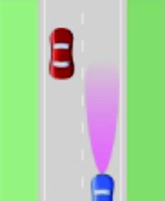
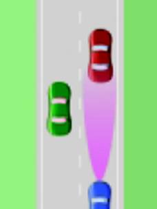
Adaptive Cruise Control (ACC) and Forward Collision Warning (FCW) systems require an ability to resolve and identify robustly the existence of both stationary and moving 'target' vehicles that are in the motion path of the Host vehicle. The performance of these systems is affected by their ability (a) to estimate the relative inter-vehicular path motion (i.e.: range, relative speed, radius of curvature, etc.) between the host vehicle, the roadway ahead of the host, and all of the appropriate targets (i.e.: roadside objects, and in-lane, adjacent lane, and crossing vehicles, etc.); and (b) to predict the mutual intersection of these motion paths. In addition, these systems must be robust in the presence of various types of driving behavior (e.g.: in-lane weaving/drift, lane change maneuvers, etc.) and roadway conditions (e.g. straight roads, curved roads, curve entry/exit transitions, intersections, etc.) that are encountered in the 'real-world' environment.
The target selection approach pursued used a single active forward looking radar sensor augmented with a yaw rate sensor. The forward-looking radar sensor provided target range, range rate, and angular position information. The yaw rate sensor was used to estimate the roadway curvature ahead of the Host vehicle. Delphi's first generation target discrimination algorithms were used to identify overhead bridge objects and to discriminate between moving cars and trucks. The Target / Host kinematics were evaluated to determine target motion status (i.e.: oncoming, stopped, moving, cut-in and cut-out, etc.), and geometric relationships were employed to determine which of the valid roadway objects fell within the Host's forward projected path. The improved algorithms yielded very good results, but they were prone to false alarms during curve entry/exit scenarios and during host lane changes.
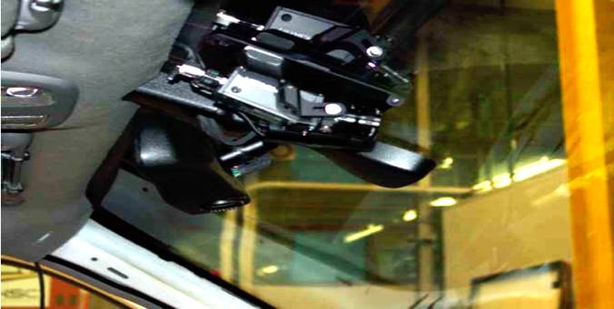
The overall goal of the Forward Vision Sensor is to facilitate the development of a robust, real-time forward looking lane tracking system to enhance the overall forward Path Estimation and Target Selection algorithms. The system consists of two components. A video camera, mounted behind the windshield of the vehicle, will acquire images of the roadway ahead of the host. A remotely located image processing unit will then detect and track the position of the lane boundaries in the images, and will provide a model of the changing road geometry. In addition to road shape, the lane tracking system will provide estimates of lane width and of the host's heading and lateral position in the lane. In the Data Fusion Module this information will be fused with road and host data from other sources, such as Scene Tracking and GPS Map, to provide more accurate estimates of road and host state to the Target Selection Module
Although many different vision-based lane detection and tracking systems have been developed worldwide, their primary focus has been on applications such as lane departure warning and lane keeping, where the required range of operation is usually less than 25 meters. Host heading and lateral lane position derived from such systems can be used to reduce the effects of driver hunting and host lane changes on the task of in-path target selection, but the more serious problems associated with curve entry/exit scenarios remain. To address these, an accurate prediction of the roadway geometry up to 100 meters ahead of the host is desired. The goal of this task was to develop a vision-based lane tracking system that will provide these long-range road curvature estimates as well as complement the Scene Tracking and GPS approaches under development in Tracking and Identification Task.
To develop the robust vision system required for this program, and to take advantage of existing automotive vision technology, three short-range real-time lane tracking systems were identified as potential starting points for this task. Selection of these systems was based on their developer's demonstrated competency in the development, integration, and road testing of these systems, and on their willingness to extend their system to meet the goals of this program. Teams from the University of Pennsylvania (U-Penn), Ohio State University (OSU), and the University of Michigan – Dearborn (UM-D) were each contracted by DDE1 to further the development of their respective systems.
The NHSTA states certain requirements for the system which analyze the road. The requirements state that the system should provide host and road state estimates to within these specified one-sigma accuracy requirements:
1. Lateral position in lane: < 0.2 meters
2. Lane width: < 0.2 meters
3. Heading: < 0.2°
4. Road Geometry: < 0.75 meters at 75 meter range2
The Forward Vision Sensor should produce confidence estimates (which may be a function of range) for the road-geometry and host vehicle state. The system should also report the number of lane markers (i.e. left, right or none) that it has acquired as well as some indication of when a lane change event has occurred. The minimum update rate is 10 Hz with an initial maximum acquisition time of 5 seconds. The system should work on the freeways, freeway transitions, expressways and parkways where the minimum horizontal radius of curvature is 300 meters, and when the host speed is between 25 and 75 mph. The system will operate in clement weather, in both day and night conditions, and under natural and artificial lighting.
The road surface should be paved, clear, and free from glare, and the road markings should have good contrast. The lane markings can be of single or double lines that are either solid or dashed. A Vision EDV was configured as a test bed for the development and evaluation of the lane tracking systems. GM supplied a 1996 Buick which was outfitted by DDE with a CCD-camera, CAN bus, speed and yaw rate sensors, a vehicle interface processor to format and transmit the vehicle data on the CAN bus, and the video encoder system described above.
This vehicle was provided for the shared use of all vision teams, and has been driven by each to collect the video scenarios that are currently being used for system refinement and validation. During the down-select process, each of the vision systems can be integrated into the vehicle, and data collected from each simultaneously. It requires a 233MHz Pentium MMX processor to process these data collected from the sensors.
| Are you interested in this topic.Then mail to us immediately to get the full report.
email :- contactv2@gmail.com |
